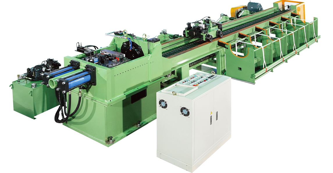
Cold drawing machine reduces the diameter of metal tubes, rods and bars to meet various industrial demands. It is commonly applied to steel pipes, requiring strict precision and re-sizing.
The resulting product exhibits high mechanical properties, good machinability and precise dimensional tolerances. The drawing process is carried out at room temperature, with the lead end of the bar or rod coil forced through a die.
Wire Drawing Process
The process of cold drawing involves pulling a rod or wire through dies that reduce its cross section. This is a highly energy-consuming operation that relies on both tensile and compressive forces to deform the steel material, and it must be performed at low temperatures to limit damage to the material.
This force must be sufficient to overcome friction and the material’s resistance, but it is limited by the yield strength of the steel material. While most analyses of the process treat the average die pressure as uniform, sophisticated drawing analysis shows that the pressure is much higher near the channel entrance and exit than in the middle.
Redundant work and frictional work increase as the draw angle decreases, so optimum die angles minimize both to reduce force requirements and to improve surface quality. The use of proper lubrication is also crucial in the wire drawing process to reduce friction and unnecessary deformation, and it must be applied continuously during the drawing operation.
Wire Sizing
To reduce the diameter of steel wire, metalworking companies use cold drawing. This process involves drawing the raw material multiple times through a series of dies with decreasing size to create the final shape. The material is often annealed before, during (between passes), or after the drawing process to increase ductility and remove internal stresses.
Before beginning the drawing process, the raw material is submerged in lubricant to prevent it from sticking to the die. The lead ends are also reduced in size so that they can fit through the die more easily.
Schmidt Maschinenbau GmbH offers single wire drawing machines that are specially designed for your production line. They can be equipped with an adjustable gimbal and rotating, water-cooled final drawing capstan to achieve high wire quality. They can also be programmed for various electrical code standards.
Wire Forming
Round metal lengths ranging from rod to bar stock are referred to as wire and may be subjected to the cold drawing process. This process reduces the diameter and shapes the wire to be used in a variety of industries.
Manufacturers then use tools to give the metal wire more shape. This can include bending the wire left or right, up or down, angling it and creating coils. These shapes can be welded together or cut to create parts for various industries.
The final step involves swaging or pressing the end of the wire. This reduces the diameter of the ends so that they can be easily inserted into the die. The swaging process also creates a smooth finish on the ends of the wire. The resulting end can be flattened, grooved, or twisted to create button, carriage, or collar headings.
Wire Drawing Die
The dies on the wire drawing machine are a key element of the process and must be manufactured and maintained to the correct geometry. This will reduce overall die costs, improve wire quality and shorten production time.
In order to achieve accurate cross sectional areas the die must be cooled, lubricated and rotated during the draw cycle. This helps reduce die wear, thermal cracking of the die and work hardening of the metal being drawn.
The die has a bearing portion that consists of a parallel portion that is equal to the final wire diameter (Little less or more depending upon material being drawn, harder materials will tend to spring back and make die larger than desired, while soft material will draw out to final diameter after leaving the die). Optimum bearing length is selected for each application according to die design, material being drawn and the level of lubrication required. There are a number of good technical papers on this topic and practical experience coupled with testing and simulation software can guide the selection of an optimum bearing length.


